UI Modules
This guide describes the UI features you see in two sections. The first section describes what is common when using a device or simulator target. The second part describes what features are specific to using a simulator target.
Modules for Both Simulator and Device Targets
This section describes what UI modules are visible whether you use a simulator or a device target. The data displayed are changeable if you're using a simulator target, but read only for device target.
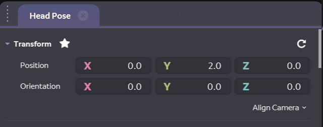
Head Pose Panel
The Head Pose panel represents the position, orientation, and state of the headset.
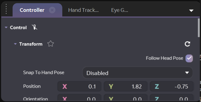
Controller Panel
The Controller Panel represents the position, buttons, and touchpad inputs of the controllers. You can choose Snap To Hand Pose to either left or right hand, which means the controller will be held by that hand and move with that hand. You can also disable this feature and check the Follow Head Pose box instead, which will make the controller stay in position relative to the head pose.
Changing Position for Controller
The panels for Controller have X, Y, and Z settings for position and orientation. You can manually enter values for these. Or, you can click on one of the letters and drag the mouse side to side to change the values.
Actions
A touchpad touch registers only when the z (force) value is greater than zero. You can also send button presses.
Touchpad Gestures
You can perform swipes and other touchpad gestures.
- Set the Gesture Type.
- Change the Touchpad Gesture State to Start, and then change it to End.
- Set the Gesture Direction.
Hand Tracking Panel
The Hand Tracking panel represents the position, orientation, and recognized static hand gestures.
For each selected gesture, your app receives notice of the recognized gesture, the confidence value, and the world coordinates (position and orientation) of the gesture.
A gesture with a confidence value of 0 is still a detected gesture. To indicate no detected gesture, click the no-hand gesture.
The Simulator detects gestures and key points outside the meshing frustum. This is by design, but remember that on device, gestures outside the meshing frustum are not detected.
Changing Position for Hand Tracking
The panels for Hand Tracking have X, Y, and Z settings for position and orientation. You can manually enter values for these. Or, you can click on one of the letters and drag the mouse side to side to change the values.
Eye Gaze Panel
The Eye Gaze panel represents the vergence point and the positions of the eyes.
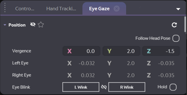
The eye positions are the positions of the center of the eyes as would be reported by the eye tracking cameras.
We do not make any effort to correlate the vergence position with the values you enter for your eye position. You can set them independently and it is up to you to enter realistic values.
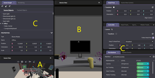
Modules for Simulator Targets
- A: Scene View
- B: Device View
- C: Tool Panels
You can hide or reveal panels, including Scene View or Device View, using the panels menu.

Primary Navigation Target Menu
Using this menu you can select the primary target of navigation.

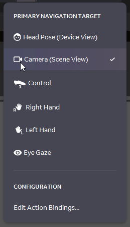
To learn more about Primary Navigation Targets see Action Bindings and Input Mapping.
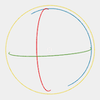
A - Scene View
Scene View depicts all the entities in the scene. The red lines represent the meshing frustum used in the Simulator.
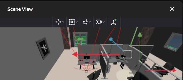
Scene View Toolbar
Manipulation Mode
| Icon | Description |
|---|---|
 | Manipulates selected objects. |
 | Moves the selected objects. |
 | Rotates the selected objects. |
 | Scales the selected objects. |
Anchor Mode
| Icon | Description |
|---|---|
 | Set the gizmo transform pivot point to the object base. |
 | Set the gizmo transform pivot point to the object center. |
Reference Mode
| Icon | Description |
|---|---|
 | Set gizmo transforms to be relative to local object coordinates. |
 | Set gizmo transforms to be relative to world coordinates. |
Scene View Camera Mode
| Icon | Description |
|---|---|
 | Shows a birds-eye view of the room contents in the Mini Map. |
 | Free Fly Camera |
 | Resets the camera to its starting position. |
Gizmos
| Icon | Description |
|---|---|
 | Select which gizmos to show, such as cache grid, compass, or hands. |
Editing Objects in the Scene View
If you want to move, rotate, or resize any of the objects in the room:
- Click the object in the Scene View to select it. A bounding box is drawn around the object.
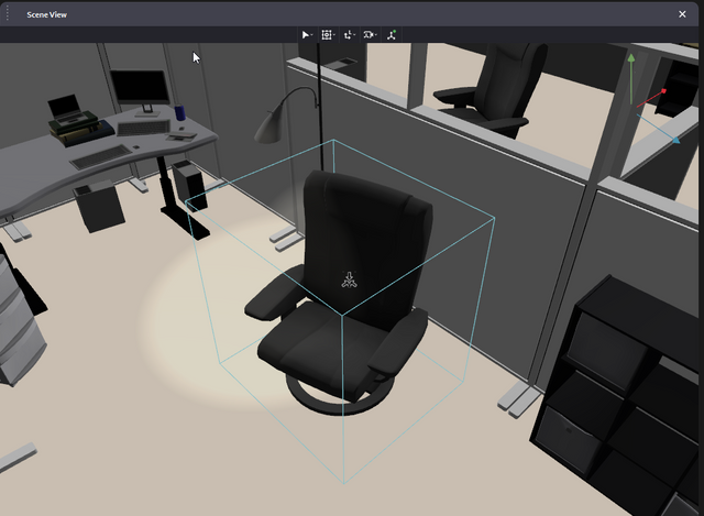
- Set your manipulation mode in the toolbar, or press one of the hotkeys described in Action Bindings. Ensure you're manipulating the object in the correct transform space by toggling pivot or orientation.
- Drag the controls on the gizmo to transform the object accordingly. The Headset, Control, and other Magic Leap API placeholders can be moved and rotated, but not resized.
| Move Gizmo | Rotate Gizmo | Scale Gizmo |
|---|---|---|
 |  | ( |
- Or, directly edit the Position, Orientation, or Scale of the object in the Scene Graph panel.
B - Device View
This composites the graphics from the eye buffers with a view of the scene as seen from the point of view of the headset.
C - Tool Panels
The panels provide various features.
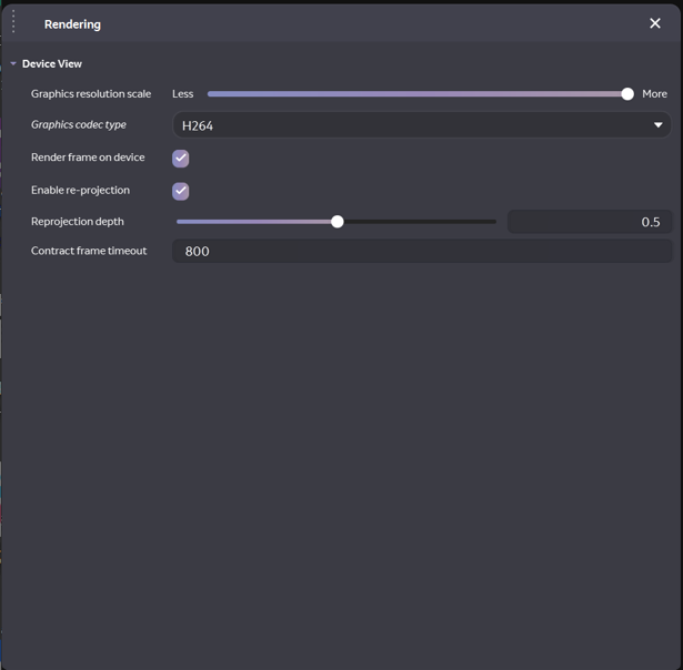
Rendering Panel
The Rendering panel displays parameters that control how the views are rendered.
Scene Graph Panel
The Scene Graph panel allows you to load new virtual rooms or custom models, or edit the objects in the scene.
Scene Graph Toolbar
| Icon | Description |
|---|---|
 | Load Virtual Room – You can load any .room file exported from the Virtual Room Generator or any session that has been converted to a .room file using the Package Session as Room option in the Session drop down. |
 | Add Model – You can import individual 3D objects into your virtual room. The following formats are supported: .3ds 3ds Max; .ase 3ds Max; .blend Blender 3D; .dae Collada; .fbx Autodesk 2014/2015, not 2016+; .obj Wavefront; .ply Stanford Polygon Library; .gltf, .glb GL Transmission format |
 | Clear Virtual Room |
Create a Room
You add to the virtual room layout by selecting the Add Room button in the Scene Graph panel's toolbar.

If you want to completely replace the room, click the Clear Scene button, and then the Add Room button.

Virtual rooms are created in the Room Generator tool.
Moving Around in Application Simulator
You can move the hands and controller as a unit to walk around the room using the arrow buttons on your keyboard. If you hold down both mouse buttons, you can turn side to side to view other areas of the room.
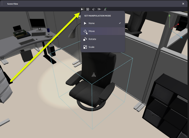
Changing Position for Objects in the Room
Using the Scene View panel, you can click on an object and then use the arrows in the image to pull the object in different directions. You can click the Set Manipulation Mode icon to choose whether to move, rotate, or scale the object differently.
You can also choose an object from the the Scene Objects panel and then move it around in the Scene View.
Properties
Select an object in the Scene Graph or in the Scene View. The properties of the selected object will be shown in this panel and you can change them as needed.
Scene View Camera Panel
Position values are given in meters.
Orientation values are given in degrees.
Check boxes are boolean toggles for the associated property: selected is true, clear is false.
To change the value of any numeric property:
Click inside the field, type the new value, and then press Tab or Enter.
-or-
Pause on the label of a field. When the pointer changes to a ↔, drag the pointer to change the value.
Marker Tracking Panel
The Marker Tracking panel enables you to add and remove markers in the virtual room, and edit attributes of the markers. For more details about this panel, see the Marker Tracking guide.
Permissions Panel
You can see permissions you granted or denied for your application in this panel. If you need to change the settings, you can by clicking on the green drop-downs and choosing whether to grant or deny a permission.
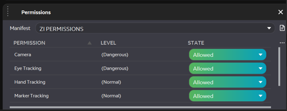
The Permissions panel provides the ability to set states for several permission areas supported by the MLSDK. The permission states (Allowed, Denied, Pending) are enforced during ML API invocations, as documented in API headers.
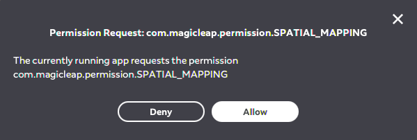
When an API finds a permission state to be in Pending state, it signals the UI to generate a popup that lets the user allow or deny the permission.
The UI lets you load a manifest file that filters available permissions to those specified in the file. All permission requests that are not specified in the manifest are denied. Two pre-defined filters, ZI PERMISSIONS and ALL PERMISSIONS, are also provided. The former filters permissions to areas supported by the Application Simulator, whereas the latter filters to all permissions in the MLSDK.
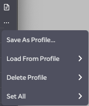
All permission states can be saved in a named Profile and persist across Application Simulator sessions. The UI also has a ... button that brings up a menu to save, load, and delete profiles. Additionally, all permission states can be set to allowed, denied, pending, or default. When set to default, all normal permissions state are set to allowed state, whereas all dangerous permissions are set to pending state.
The permissions panel allows you to test workflows that require specific Dangerous permissions from the Application Simulator workflow in a more convenient way than on device, which requires fully uninstalling your app to test.
That said, the default behavior is to allow all permissions recognized by the Application Simulator, so that you can opt into the workflow as needed.
When developing ML C API applications, since the Application Simulator does not simulate the AOSP Java runtime, you should conditionally replace the AOSP Java APIs with corresponding C API calls from ml_zi_permissions.h. When developing Unity scenes, the ML Unity SDK will automatically prompt for these permissions as needed via the Magic Leap Hub or Unity Editor.
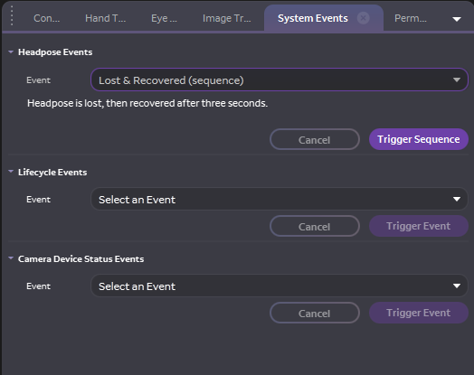
System Events Panel
The System Events panel provides the ability to trigger various System Events that the device can generate under different conditions. Common System Event sequences have been provided that attempt to mirror the behavior of the event cycles on the real device. Individual events can also be triggered manually.
Simulator Limitations
We verify that the values you enter are valid, but not whether they are realistic. That is so you can make sure your app can handle edge cases or seemingly nonsensical API data.
Audio
Applications exercising ML Audio APIs can play audio both on host and device. Audio input and analysis support is not implemented.